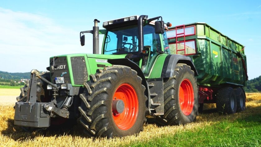
Starting in 1995, when Fendt introduced its “Favorit 926 Vario” with 260 horsepower at the German Agritechnica trade fair, tractors with continuously variable transmission began to spread throughout the sector, eventually becoming a technological must-have.
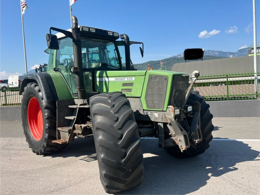
If the saying “When the going gets tough, the tough get going” holds true, it is equally true that in 1995, Fendt proved itself by responding to a difficult period for the entire German tractor industry. That year, the company launched the “Favorit 926 Vario,” the first high-power agricultural tractor (260 hp) equipped with a continuously variable transmission and mass-produced. Initially met with skepticism by most industry professionals, the market quickly demonstrated its appreciation, transforming it into an essential technological feature for all manufacturers.
The 1995 launch marked a turning point for the entire industry, positioning Fendt as a technological leader and cementing Germany’s and Europe’s supremacy in tractor transmission technology. For years, European manufacturers had gradually improved mechanical transmissions without pursuing advanced research, leaving U.S. manufacturers to lead in innovation.
Mechanical and Hydrodynamic Variable-Speed Drives
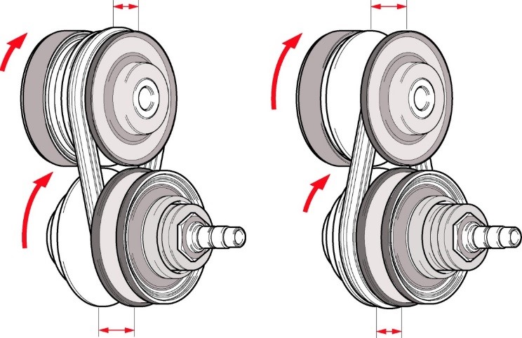
Continuously variable transmissions (CVTs) have origins dating back to the early days of the automotive industry. Studies aimed at defining solutions for automobiles led to the development of various types of speed variators, starting with belt and pulley systems. These worked by changing the radius of two pulleys—the driving pulley connected to the engine and the driven pulley linked to the wheels.
The most common system, with a fixed center distance between the pulleys, consisted of a V-belt running around pulleys made of adjacent metal disks. By moving the disks closer together or farther apart, the diameter on which the belt rests changed, thereby adjusting the transmission ratio between the driving and driven pulleys.
Both pulleys were adjustable:
- The driving pulley was controlled by a mechanical, hydraulic, or electric actuator.
- The driven pulley was managed by a spring that automatically responded to the working diameter of the driving pulley.
Initially made of leather, then synthetic materials, and today Kevlar, the belt served as a traction element. The simplest purely mechanical versions found widespread use in two-wheel vehicles, particularly scooters.
In agricultural machinery, belt variators were used in combine harvesters until the 1980s and are still found in mid-sized machines produced in China. However, the power limitations of belt variators led to their replacement by chain variators in automobiles. These systems used a metal chain with interlinked plates that contacted the pulleys instead of a belt.
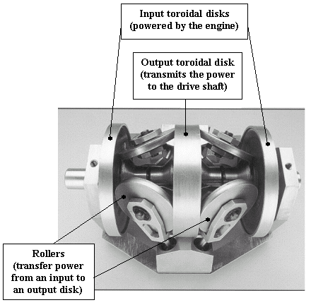
Working in an oil bath, the chain functioned as a pushing element, ensuring greater durability than a belt. However, in tractors, chain variators never progressed beyond the prototype stage, much like ToroTrak friction variators. These consisted of two pairs of disks forming a toroidal chamber containing three cylindrical rollers with adjustable axes. Each roller engaged with the adjacent disks, transmitting movement from one disk to the other. By tilting their rotation axes, the contact diameters between the rollers and the disks changed, modifying the transmission ratio.
Despite their operational effectiveness, friction variators suffered from energy losses, similar to hydrodynamic variators, which ultimately led research toward hydrostatic variators.
Hydrostatic Variable-Speed Drives
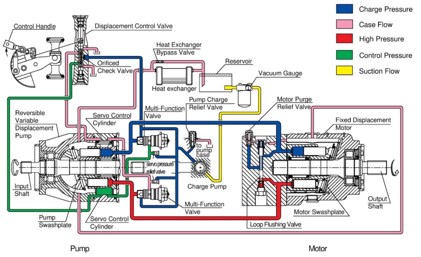
A hydrostatic variator consists of:
- A variable-displacement hydraulic pump, driven by an internal combustion engine.
- A fixed or variable-displacement hydraulic motor, powered by pressurized oil from the pump.
The system operates in a closed circuit. In versions with a fixed-displacement motor, the transmission ratio is adjusted by changing the pump’s displacement, which alters the oil flow rate and, consequently, the motor’s speed.
Displacement variation is achieved by modifying the tilt angle of the swashplate, which moves axial pistons:
- When perpendicular to the rotation axis, the pistons stop, blocking the hydraulic flow.
- At maximum tilt, the pistons move through their full stroke, generating maximum hydraulic flow.
Alternatively, the entire pump or motor body can be tilted, though the principle remains the same. The swashplate, also known as a tiltable plate, is adjusted by a mechanical control and can be tilted in both directions, enabling reversal of hydraulic flow and motor rotation.
Energy conversion
Since hydrostatic transmissions involve two energy conversions (mechanical → hydraulic in the pump, then hydraulic → mechanical in the motor), their efficiency is lower than mechanical transmissions, partly due to hydraulic losses. However, this is offset by operational advantages and easier tractor installation.
By the 1950s, hydrostatic systems were being used in earthmoving machines. International Harvester played a leading role, introducing a turbine-powered tractor with a hydrostatic transmission in the early 1960s. In 1967, they mass-produced the “656” model, an 80-hp hydrostatic tractor with a variable-displacement pump and motor.
Study and technology
Despite a 73–75% efficiency (compared to 85–87% for mechanical transmissions), its stepless speed control and ease of use proved valuable for low-power applications. Over time, this led to hydrostatic transmissions being widely adopted in:
- Compact garden tractors (<50 hp) due to their simplicity.
- Large harvesters (e.g., combine harvesters) because traction power represents a small fraction of total installed power.
- Telehandlers, particularly compact models, where precise speed control is crucial for load positioning.
CVT (Continuous Variable Transmission)
CVT systems were developed to apply the “power split” principle to tractor transmissions, overcoming the efficiency and power limits of conventional variators. A CVT transmits power through two parallel systems:
- A variator
- A mechanical gearbox
Only part of the power passes through the variator, while an epicyclic gear system distributes power flows, with control either at the input or at the output.
- Input-controlled CVT (Torque Splitter):
- Engine torque is split into two paths, driving a hydraulic machine and the sun gear of the planetary set.
- The second hydraulic machine drives the ring gear, while the output occurs at the planet carrier.
- At lock-up point, the ring gear stops, and power flows entirely through mechanical gears, maximizing efficiency.
- Output-controlled CVT (Speed Splitter):
- The engine drives both the sun and ring gears.
- One hydraulic machine is connected via gears, while the second is coupled to the output shaft.
- Two lock-up points exist, ensuring higher efficiency over a wide speed range.
Neither system is inherently superior; the best performance is achieved when a power split group is designed to operate in the most efficient speed range. Since no single group can cover all tractor speeds, a range reducer must be added.
The higher the proportion of mechanical power transmission, the greater the efficiency. The lock-up point is strategically positioned near critical operating speeds, and optimizing the entire kinematic chain further enhances efficiency.
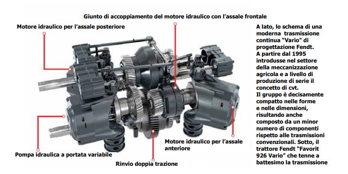
Fendt Vario ML 200
The “Vario ML 200” transmission was installed in the “Favorit 926 Vario” model in 1995, marking the debut of the “Vario” system. This innovation has since evolved and is now available in various configurations across all Fendt tractors. The core of this transmission was an electronic control system, making the tractor extremely easy to operate while introducing entirely new functionalities.
The tractor was operated via a multifunction lever. To start from a standstill, the operator simply moved the lever forward and held it until reaching the desired speed. To reduce speed, the lever was moved backward, while changing direction required a movement from right to left.
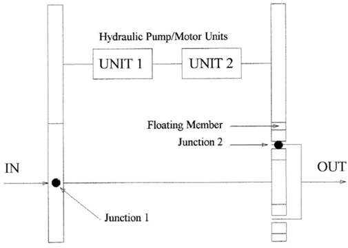
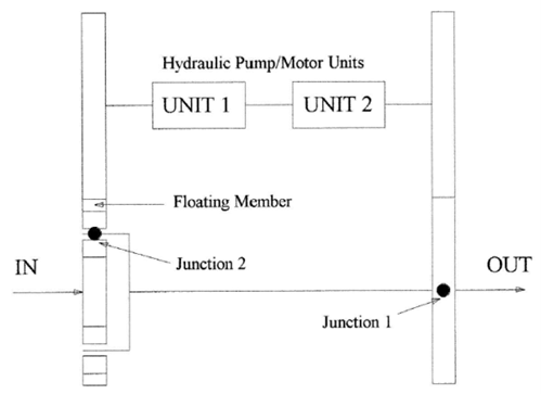
From a conceptual standpoint, the “Vario ML 200” transmission operates on an output-controlled power split system. During startup and at near-zero speeds, 100% of the power is transmitted hydrostatically. However, at maximum speeds within each of the two ranges, the hydrostatic power transmission is eliminated. The “L” range reaches 32 km/h, while the “H” range achieves 50 km/h, with both speeds corresponding to the lock-up point.
In the field, the tractor primarily operates in the “L” range, eliminating the need for range shifts. On the road, it functions in the “H” range. However, in specific situations—such as steep inclines with a heavy trailer—the system requires a shift to the “L” range. To facilitate this, the “Automatic Shift on the Go” function enables range shifts while in motion at speeds close to 20 km/h.
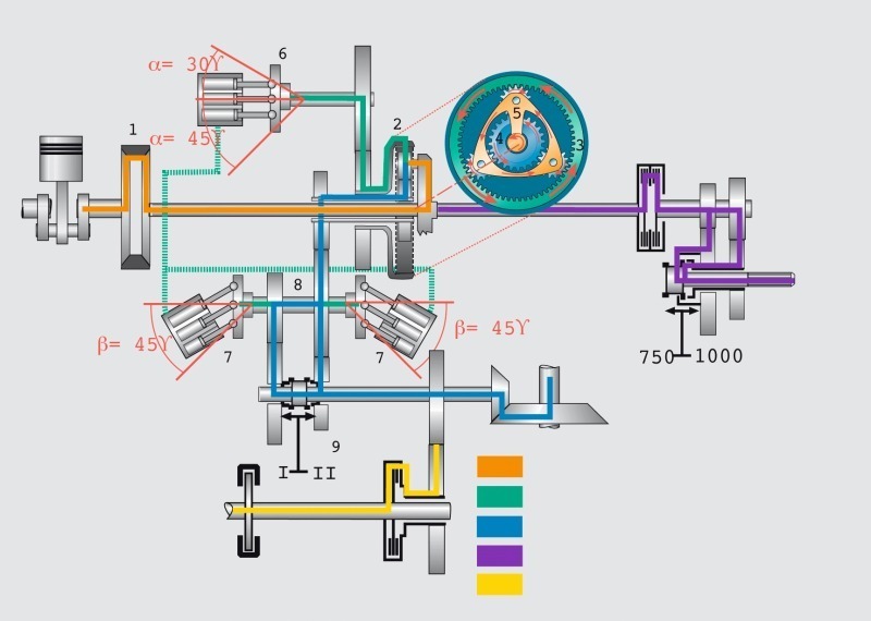
Reverse speeds are achieved by leveraging the variable transmission functionality in both directions, eliminating the need for an additional reverser. Given that hydrostatic power transmission is significantly high at low speeds, the pump and motor displacement requirements exceed those of other CVT transmissions. To address this challenge, Fendt developed specific components, including a swashplate pump and motor capable of reaching a 45-degree tilt angle, along with two parallel hydraulic motors.
Following the “Vario ML 200”, Fendt developed additional CVT transmissions for lower-power tractors, starting with the 700 series and extending to specialized 200 series models. While a single motor is used for medium and low-power tractors, the swashplate pump and motor system remains a standard feature across all Fendt transmissions.
Overall, the mechanical structure of the Fendt transmission is complex in its pump and dual hydrostatic motors, yet remarkably simple and rational in construction due to its minimal component count. According to DLG tests, the transmission efficiency curve shows values just below 85% within the 5-20 km/h speed range, with minor penalties at extreme speeds due to the higher proportion of hydrostatic power transmission.
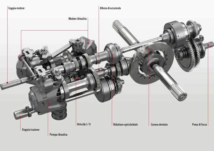
Steyr S-Matic
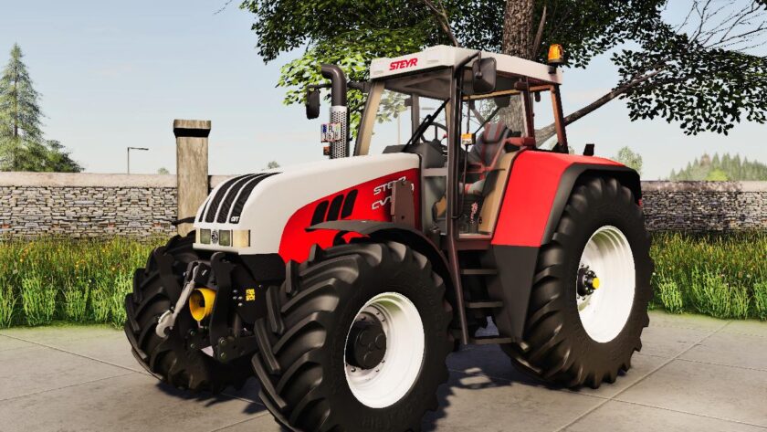
During the 1990s, multiple manufacturers developed continuously variable transmissions (CVTs). The Austrian manufacturer Steyr introduced a concept in 1994, later evolving into the “S-Matic” transmission after CNH acquired the tractor division and ZF took over the transmission division.
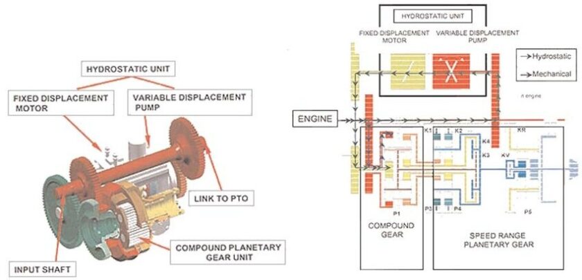
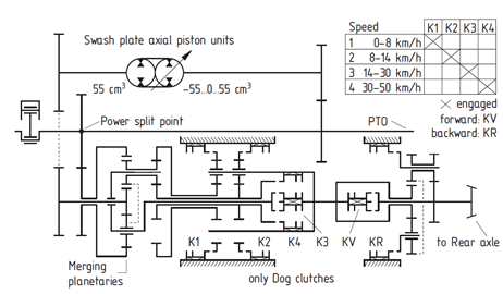
The primary objective of Steyr’s engineers was to maximize the percentage of mechanically transmitted power. This was achieved through an input-controlled power split system, which limited hydrostatic power transmission to a maximum of 50%. The system featured four ranges, a conventional hydrostatic unit with a back-to-back axial piston pump and motor, and a planetary reverser installed at the rear of the range assembly.
The transmission layout includes a five-shaft planetary group, followed by two standard planetary sets with mechanically engaged ranges. A specific sleeve mechanism ensures seamless engagement when both elements rotate at the same speed. This system eliminates power discontinuities during range shifts and overlapping speeds between adjacent ranges.
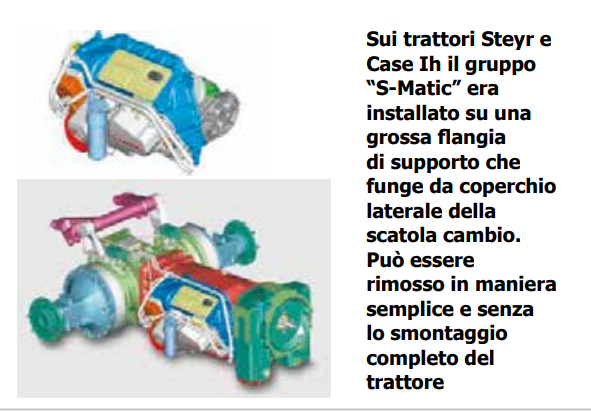
The entire variator assembly, called the “cartridge”, can be removed from the right side of the transmission without separating the engine from the gearbox. This design is possible because the cartridge is mounted on a large flange, serving as a side cover for the gearbox housing.
The efficiency curve appears as a series of four curves, each corresponding to a single range, with efficiency exceeding 80% at speeds above 4 km/h. The transmission, available on Steyr and Case IH models, features “Active Hold Technology”, which keeps the tractor stationary on slopes without using brakes, utilizing an electronic control system to generate a counteracting torque.
Zf Eccom 1.5
Before acquiring Steyr’s transmission division, ZF had developed a CVT transmission family for various tractor power ratings. The “Eccom 1.5” handled up to 150 hp, the “Eccom 1.8” up to 180 hp, and the “Eccom 3.0” up to 300 hp.
The first production tractor equipped with an “Eccom 1.5” transmission was the Deutz-Fahr Agrotron TTV, featuring a custom rear axle designed by Deutz-Fahr to reduce energy losses—particularly from brakes and the pinion/crown gear assembly.
Conceptually similar to Steyr’s “S-Matic”, the ZF “Eccom 1.5” uses multi-disc wet clutches for engaging its four ranges. The hydrostatic power transmission never exceeds 40%, and the reverser is positioned downstream of the range assembly, using two multi-disc wet clutches.
The transmission offers three operating modes:
- Automatic Mode: Speed is controlled via the accelerator pedal or hand throttle, while the electronic system adjusts engine speed and CVT settings based on load.
- PTO Mode: Automatically activates when the power take-off (PTO) is engaged, maintaining a constant engine speed for PTO-driven implements.
- Manual Mode: The operator sets engine speed via the throttle, while the gear ratio is adjusted using a control lever.
Additionally, the “Stop & Drive” function allows the tractor to remain stationary on inclines, even when loaded, without requiring brake application.
ZF introduced the “Eccom 1.5” transmission to the market nearly simultaneously with the Agrotron TTV launch. Shortly thereafter, John Deere debuted its first CVT models, the “6000 AutoPowr” series, equipped with ZF “Eccom 1.8” transmissions.
From that point, many manufacturers began offering high-power tractors with ZF continuously variable transmissions, alongside power shift alternatives. This trend has established CVT technology as the standard for high-horsepower tractors (200+ hp), while also becoming a premium option for lower-power machines.